Background
As a part of the HYLOW project, members of the sustainable energy research group (Gerald Muller and William Batten) have worked on the design and development of a free stream floating energy converter. Within the HYLOW project the machine has been tested at various scales by both the SERG and the Coastal Engineering Research Group & Faculty of Mechanical Engineering & Marine Technology at the University of Rostock, Germany.
Concept
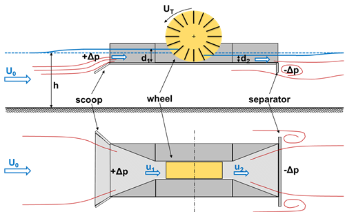
Principle of the free stream energy converter, showing the solid base, contraction and separator, used to generate a local head difference.
Boat mills were a common site on many large rivers throughout Europe from medieval times until they were phase out in 20th century during the industrial revolution. However, today there is a new requirement to extract energy from free stream currents. The research presented is based upon developing the classic designs, which separated the design of the wheel from the hull forms, to a new design that uses the hull form to improve the performance of the wheel.
In order to extract energy from a river the wheel must rotate at velocity slower than the free stream velocity. To improve efficiency the developed design produces a head difference across the wheel shown in the schematic above. This is achieved by using:
- a scoop and contraction in the front to increase pressure
- a separator at the back to reduce pressure to maintain a lower water level behind the wheel
Small scale tests
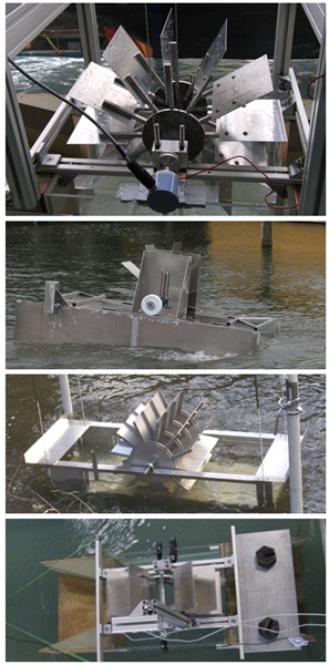
Various models testing during the development
An extensive series of tests has been performed with a range of models tested under various conditions. Experiments have been carried out in three different flumes, a towing tank and in open water. The results from these tests have been used in order to establish optimum geometries for the floating energy converter and the design of the Large Scale Model.
The results have demonstrated the significance of:
- Wheel rotational speed
- Clearance gap between wheel and base plate
- Bow and stern geometry
- Effect of separator and scoop
- Influence of model draft
- Tank depth and blockage
- Hull Pitch angle
- Directional stability
Large scale model deployments
A large scale model with a wheel diameter of 3.2 m, a length of 7.6 m and a beam of 2.4 m has been designed and developed to understand scaling laws and assess the environmental impact. The wheel has 12 steel blades and the power is dissipated using a disk brake. The reaction on the callipers is used to measure the shaft toque for the experiments. Performance tow tests have been conducted in a naval base at Rostock and in the Warnow river (shown above) for environmental assessment.

Large scale tests of 7.6m length model on the Warnow river Germany
Comparison of model scales
The figure below compares results from some of the large scale model towed in calm water, and the small flume model floating at two different pitch angles. The plot includes a range of different set-ups and shows comparable results
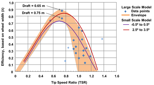
Efficency of both the small scale and large scale models of the FSEC
Plausible 10kW sizes
The table below shows the current design scaled for 10kW for four different free stream speeds.
| Flow Speed (m/s) | 1.4 | 1.6 | 1.8 | 2.0 |
| Wheel Width (m) | 3.3 | 2.7 | 2.2 | 1.9 |
| Paddle depth (m) | 2.2 | 1.8 | 1.5 | 1.3 |
| Wheel Diameter (m) | 10.1 | 8.3 | 6.9 | 5.9 |
| Overall Length (m) | 9.8 | 16.2 | 13.6 | 11.6 |
| Overall Width (m) | 8.1 | 6.7 | 5.6 | 4.8 |
Further details
- Batten W.M.J. and Müller G.U. (2011), Potential for using the floating body structure to develop head difference to increase the efficiency of a free stream energy converter, Proceedings of 34th International Association of Hydraulic Engineering & Research (IAHR) Biennial Congress, Brisbane, Australia, June 16 – July 1, 2011.
- Batten W.M.J., et al. (2011), Design and stability of a floating free stream energy converter, Proceedings of 34th International Association of Hydraulic Engineering & Research (IAHR) Biennial Congress, Brisbane, Australia, June 16 – July 1, 2011.
- Weichbrodt et al (2012), Großmaßstäbliche Modellversuche mit einem schwimmenden Energiewandler“ in Korrespondenz Wasserwirtschaft, May 2012.