Main User (Student) Use Case Diagram v1.0

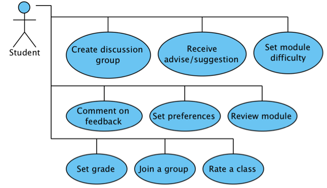
One of the main feature of a system is the interactivity between it and its users. The interaction is illustrated by using use case diagram. Here we represent the main actor of the system where the entire system is mostly used and interacted with by this user, student actor.

The diagram shows how the student will interact with module review social network and what actions he/she will perform. The other actors are not included in this version of use case diagram because at this point their interactivity with the system is very limited at this stage. These actors are the lecturer who can comment on review or reply on a comment. The system which analyze the student input as preferences and generate a suggestions or a list of suitable module based on student grade, pre-set preferences, rating and difficulty level of a module.

UseCase

Entity Relation Diagram

Entity Relation Diagram is used to illustrate a unified view of a system data [1]. This entity relation diagram shows the main entities in LessonPlan application and how these entities relate to each others. By ensuring the correct entities data types and relation, we enforce the integrity of the database. The relationship between two tables is ensured by referencing its primary key like userid in Module_Feedback table which reference the user id who provided that feedback. If a user id does not exists in user table, it can not be stored in any other table which reference it. This is to enforce the referential integrity in database. To enforce the entity integrity, a primary key in each table has been identified. These primary key might be single attribute like userid in users table or composite primary key (consists of multiple attributes together) like mode_program table.

In ERD, U stands for unique in that table and N stands for nullable (can be null). To ensure that an email address is not used by two or more users, the attribute constraint is set to be unique. Same for school name, module name and program name as we can not have the same name which represent two schools, modules or program. The grade in user table is set nullable so the user will have the ability to choose between giving it or not.

These tables represents only LessonPlan database without the integration with university database in which the system can query from using remote procedure calls.

ModuleReview


———-

[1] Chen, P. P. S. (1976).The entity-relationship model toward a unified view of data. ACM Transactions on DatabaseSystems (TODS), l(1), 9-39.

Class Diagram v1.0

The class diagram of LessonPlan 2.0 social network illustrate the structure of this application by illustrating the classes and their attributes and operations.

LessonPlan 2.0 project consists of multiple classes in which some of them depend on others. The main class User is a generalization for both students and lecturer/module leaders. Both of them (student class and lecturer class) have something in common which is represented in User class. The other attributes and operations that distinguish student from lecturer are set in student class, same for lecturer.

The dependencies between classes are represented with doted arrows. Each class represent class name, number of attributes which set to be private by assigning – sign before them, and public constructors and operations with plus + sign before them.

Social Network Class Diagram