Building Survey
Portus is blessed by the surviving remains of many standing buildings. These remains exist up to fragments of the second floor which gives huge potential for the reconstruction of what they looked like. The standing buildings need to be treated as any other artefact and recorded on site.

Terminology
Floors
Different countries have different names for the floors of a building. Please be explicit about which system you are using when you are referring to floors – even if it refers to a plan you are drawing on the upper floor of a building:
- GB, France, Germany: Basement, Ground, First, Second
- America, Italy: Basement, First, Second, Third
Wall types
See also http://www.ostia-antica.org/dict/topics/glossary.htm for a guide.
- Opus Quadratum: Huge ashlar blocks, no mortar
- Opus Caementicium: Concrete, unfaced, often with grooves and lines from shuttering
- Opus Incertum: irregular stone facing
- Opus Reticulatum: Cones of tufa or basalt with diamond shaped ends
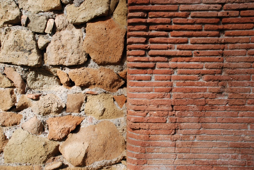
- Opus Testaceum: Brick facing
- Opus Mixtum: Reticulatum and Testaceum together
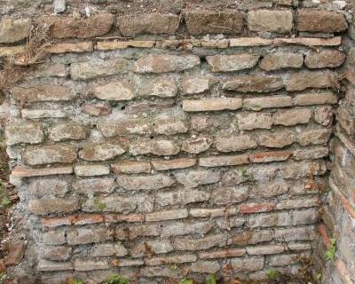
- Opus Vittatum: Alternating layers of bricks and rectangular tufa blocks
- Mortar: A mix of lime, sand and water used to bind bricks etc together. It is important to note the colour as this can represent different dates of construction. We have grey with black inclusions (possibly imported sand from the Bay of Naples), sandy coloured and whiteish.


Wall coatings
- Opus signinum: Waterproof plaster made of crushed terracotta pieces and lime
- Stucco and plaster: Lime based wall coating, applied in layers with outer layer almost pure lime, inner layer coarse with inclusions. Colours applied when wet, or painted on over the top when dry
- Floor coatings:
- Opus signinum: See above
- Opus Spicatum: Herringbone flooring of small bricks laid on their sides
- Opus Tessellatum: Mosaic or tessellated pavements
- Opus Sectile: Mosaic of irregular shapes to form geometric or figurative images
Recording
Standing buildings generally expose more than one side so recording needs to accommodate this. Recording will always include a plan of the top of the wall. This indicates the construction of the wall as it will usually show the facing type and any rubble core. Where possible this will be drawn on site but in the case of a high up standing wall, this will be done from aerial photos.
In addition to the top of the wall, usually at least one side of the wall will be recorded as if it is a section. This is used to show the type of construction of the wall, state of preservation and any traces of earlier walls, foundations, constructions methods etc. Vertical walls need to have the direction of the walls noted – usually referred to as faces. Faces can be referred to with their direction and internal/external (if known) e.g. South internal, or more usually, you can use the direction in which the wall faces e.g. North-facing. This can be the same as south internal, but is more precise if you do not know if the wall is internal or external. As with all recording, context numbers are really important and need to be assigned to everything. As with sections, make sure you have at least two 3D surveyed reference points on your drawings.
Methodology
There are three main methods of recording walls: Hand drawing (covered in section and plan drawing), Survey and Photogrammetry. In addition we are also carrying out specialist laser scanning of whole buildings.
Survey
A total station (see survey section) can be used to draw the basic elements of a wall for reference purposes. Each point taken is a 3D reference and when “strung” to form a line, this is particularly effective for recording large scale structures. Low structures will be recorded using the reflecting prism “IR”. The “RL” or red light option is exceptionally useful for recording items or points which are not reachable.
As a huge amount of data can be collected in this way, it is very important to be organised. Points that represent a continuous line, such as the top of a wall or the outline of a particular feature within the wall must have a “string code” assigned to them AND they must be recorded in the survey book with a context number and short description e.g. 110045 north facing reticulata.
Photogrammetry
Photogrammetry involves the creation of a 3D image or model by extracting depth and distance information from photographs. This requires a set of images of the same subject, each taken from a different location so the pixels can be matched in the software. Photoscan software processes all the photos to create a 3D mesh with surface textures derived from the photo colours.
Methodology
Place a photographic scale in the area to be photographed, so that it will appear in at least three photos, and will give the ability to scale the model. In addition you could add targets on the vertical faces, which can be surveyed in later.
Camera should be set to manual so that the focal length and zoom does not change during the sequence of images. As a quick way to achieve this, when you are happy with the view, take a photo using the automatic settings then change to manual without changing any settings. Camera aperture must be constant and set to F5.6 to F11 to reduce diffraction effects. The ISO setting should be as low as possible (100 probably) to reduce “noise”.
The photo sequence should be taken with a 66% overlap, working left to right. Repeat after rotating the camera 90°, then 180°, then °270.
Use of building recording in 3D reconstruction
The benefits of recording standing buildings in 3D are manifold. Primarily, Portus is a huge site and relating layers and building information of spread out surviving structures is very difficult. Therefore, knowing that wall thicknesses or floor heights, for example, change between one building and another can help with identifying different building periods or purposes. In addition, the information can be used to create full 3D reconstructions of the buildings once the different phases of activity have been identified. Very small surviving details can be very characteristic.
Producing standing building information in 2D drawings
Most of the time when you are recording a standing wall you will be looking at it so a 2D reproduction of the drawing will seem normal. This is also the tradition method of recording buildings. However, the information needs to include any walls that the view effectively slices through. For example, if you are recording one wall of a room, include a line that goes up the side of the adjoining wall, over the top and back down the other side wherever possible and name it “section” with the context number of the wall sliced through.