

1) Introduction
A classical DC Motor has only two connections and, when connected to a power supply, will continuously spin. On the other hand, a servo motor operates completely different. It is formed of four parts: a DC motor, a gear reduction unit, a position-sensing device (usually a potentiometer), and a control circuit. The servo receives a control signal that represents a desired output position of the servo shaft, and applies power to its DC motor until its shaft turns to that position. The shaft typically does not rotate freely round and round like a DC motor, but rather can only turn approximately 180 degrees back and forth.
The servo has a 3 wire connection: power, ground, and control. The power source must be constantly applied; the servo has its own drive electronics that draw current from the power lead to drive the motor.
The servo is controlled through pulse width modulation (PWM), which means that a signal which is ON only for a certain amount of time is applied, as seen in Figure 1. The duration of the positive-going pulse (time in which the signal is ON) determines the position of the servo shaft. That means, the angle is determined by the duration of a pulse that is applied to the control wire, as seen in Figure 2. The signal has a repetition time of 20ms and the duration of the ON signal is between 1ms and 2ms. A duration of 1.5ms is usually referred to as the neutral or central position (90 degree). A longer pulse makes the servo turn to a clockwise-from-center position, and a shorter pulse makes the servo turn to a counter-clockwise-from-center position.

Figure 1: Pulse Width Modulation
When these servos are commanded to move they will move to the position and hold that position. If an external force pushes against the servo while the servo is holding a position, the servo will resist from moving out of that position. Servos will not hold their position forever though; the position pulse must be repeated to instruct the servo to stay in position.

Figure 2: Angle of rotation of a servo, according to the pulse width
http://www.servocity.com/html/how_do_servos_work_.html
http://handyboard.com/hb/faq/hardware-faqs/dc-vs-servo/
2) Controlling a servo with Gertboard
The Gertboard is an add-on GPIO expansion board for the Raspberry Pi computer. It comes with a large variety of components, including buttons, LEDs, A/D and D/A converters, a motor controller, and an Atmel AVR microcontroller. In order to get the Gertboard powered from the Pi a jumper needs to be installed between the top two pins of the jumper J7 (located in the bottom right part of the Gertboard), as seen in Figure 3.
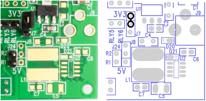
Figure 3: Header needed to power the Gertboard on
The motor controller on the Gertboard can only be used to power a DC Motor, for a servo we will need to use the Atmel AVR microcontroller to produce the control signal for the servo. To do this, we will setup the Gertboard such that the microcontroller can be programmed through the Arduino IDE. The Gertboard can hold an Atmel AVR microcontroller, a 28-pin ATmega device, at location U8 on the lower left of the board. This is usually either the ATmega 168A/PA or 328/P in a 28-pin DIP package. All input/output pins are brought out to header J25 on the left edge of the board. There is a separate 6-pin header (J23 on the left side of the board) that can be used to program the device. Note that the ATmega device on the Gertboard operates at 3.3Volts. That is in contrast to the ‘Arduino’ system which runs at 5V.
Warning: many of the Arduino example sketches (programs) mention +5V as part of the circuit. Because we are running at 3.3V, you must use 3.3V instead of 5V wherever the latter is mentioned. If you use 5V you risk damaging the chip.
Programming the ATmega
Programming the ATmega microcontroller requires a fair bit of software to be installed on your Raspberry Pi. You can use the Arduino IDE (Integrated Development Environment) on the Raspberry Pi to develop and upload code for the ATmega chip on the Gertboard, thanks to Gordon Henderson of Drogon Systems. To install all the software needed, along with instructions, you need to go to: https://projects.drogon.net/raspberry-pi/gertboard/arduino-ide-installation-isp/
To check if the software has been properly installed, power up the Gertboard from the Raspberry Pi and type avrsetup in a terminal. You will be propmpted for the type of ATmega microcontroller: 1 for an ATmega 328p or 2 for the ATmega168. If this command works OK, you should see the following:
Initialising a new ATmega microcontroller for use with the Gertboard.

Make sure there is a new ATmega chip plugged in, and press
.. 1 for an ATmega328p or 2 for an ATmega168: 1
Initialising an ATmega328p ...
Looks all OK - Happy ATmega programming!
Once this is all done, the connections seen in Figure 4 need to be done on the Gertboard to prepare it for programming the ATmega chip.
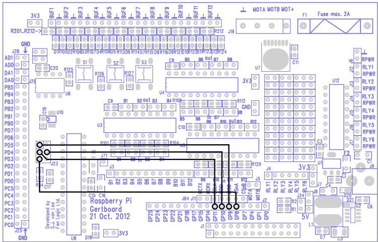
Figure 4: Connections to be done for programming the ATmega chip
To get going with the ATmega chip, start up the Arduino IDE, which should be located in your start menu, under “Electronics” and configure it following the steps from: https://projects.drogon.net/raspberry-pi/gertboard/using-the-arduino-ide/. Note the differences between the arduino and Gertboard pins: https://projects.drogon.net/raspberry-pi/gertboard/gertboard-atmega-io-vs-arduino-pins/
In order to prepare the Gertboard to control the servo, before uploading the program onto it a few more connections need to be made, as per Figure 5. The connections are:
→ PB5 on J25 is connected to B1 on J3. PB5 pin on the Gertboard is equivalent to pin 13 on Arduino, hence you will see the code works with pin 13 rather that PB5. So the pulse will be sent from PB5 to the Buffered Pin B1
→ A header attached between the two leftmost pins (labelled B1) on the connector right of C9 and below the pushbuttons S2 and S3. This will ensure that the buffer B1 is configured as an output
→ BUF1 at the top left of the Gertboard connected to the control signal (yellow wire) of the servo.
→ The GND on the Gertboard (the next right pin to BUF1) needs to go into the brown cable (GND) of the the servo
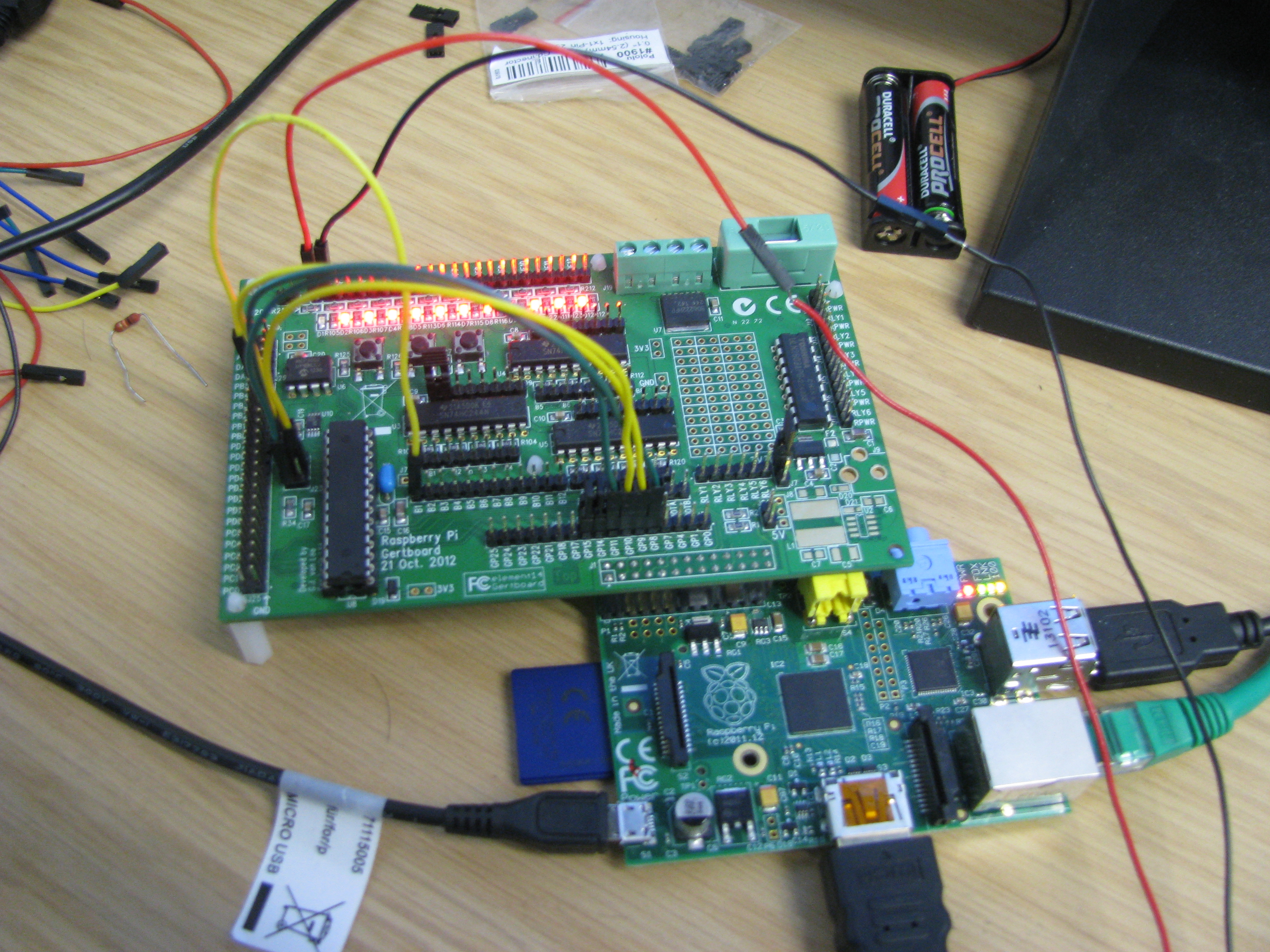 Figure 5: Connections to control the servo with the Gertboard
Also you will need power from the power supply to go into the red (middle) cable of the servo and GND from the power supply into the brown cable (GND) of the servo.
Now copy and paste the following code into Arduino IDE:
//Set the output pin
int led = 13;http://hallshome.org/rpiBlog/?p=225
unsigned int wait = 1500; //microseconds
unsigned int wait_MIN = 1000;
unsigned int wait_MAX = 3700;
int servo_dir = 1; // 1=up, -1 = down
//Servo speed
int servoSpeed = 20; // Current speed
boolean servoVariableSpeed = false;
int servoSpeedMax = 40; //Max speed
int servoSpeedMin = 5; //Min speed
int servoSpeedDir = 1; //Current direction
int servoSpeedStep = 1; //How much change the speed by
int servoSpeedTicks = 100; //keeps track of ticks remaining
int servoSpeedTicksMax = 100; //max value to reset to
int waitAtEndForTicks = 0;
int waitTicks = 50; //number of ticks to wait for at each end
//the setup routine runs once when you press reset
void setup() {
//initialize the digital pin as an output
pinMode(led, OUTPUT);
}
//the loop routine runs over and over again forever
void loop() {
//Ensure the pulse duration is within an accceptable range
if (wait > wait_MAX) { wait = wait_MAX; }
else if (wait < wait_MIN) {wait = wait_MIN; }
//Pulse the servo
digitalWrite(led, LOW); //turn the LED on (HIGH is the voltage level)
delay(20); //wait for 20 miliseconds
digitalWrite(led, HIGH); //turn the LLED off by making the voltage LOW
delayMicroseconds(wait); //wait for 1.5 seconds
digitalWrite(led, LOW);
if (waitAtEndForTicks– > 0) { return; }
if ( (servoVariableSpeed) && (servoSpeedTicks == 0) ) {
//Do we need to change direction?
if (servoSpeed == servoSpeedMax) { servoSpeedDir = -1; }
else if (servoSpeed == servoSpeedMin) { servoSpeedDir = 1; }
// Change the speed variable
if (servoSpeedDir == 1) { servoSpeed += servoSpeedStep; }
else { servoSpeed -= servoSpeedStep; }
//Reset the tick count
servoSpeedTicks = servoSpeedTicksMax;
} else { servoSpeedTicks–; } //Decrement the tick
// if (waitAtEndForTicks– >0) { return; }
//Unless we are waiting at the end, change the wait
if (servo_dir == 1) { wait += servoSpeed; }
else { wait -= servoSpeed; }
if (wait >= wait_MAX) {
servo_dir = -1;
waitAtEndForTicks = waitTicks;
}
else if (wait <= wait_MIN) {
servo_dir = 1;
waitAtEndForTicks = waitTicks;
}
}
Upload it onto the ATmega: File → Upload Using Programmer. Once the file uploads successfully, ensure that all the connections are in place, power the servo from a battery or from a power supply with approximately 6V (if using a power supply you will also need to adjust the current until the servo moves as programmed). Now that you have everything set up, the motor should spin approximately 180 degrees back and forth.
The Gertboard can drive simultaneously as many servos as the number of buffers (12) because there are enough pins to drive 12 servos. A second servo can be controlled by connecting it to a power supply and to the Gertboard in a similar fashion to the first one. Also, a few more lines of code need to be added:
int led1 = 10; //Here we use pin 10 which corresponds to PB2 on the Gertboard
pinMode(led1, OUTPUT); //Needs to be added inside the setup() routine
//Pulse the servo
digitalWrite(led1, LOW); //turn the LED on (HIGH is the voltage level)
delay(20); //wait for 20 miliseconds
digitalWrite(led1, HIGH); //turn the LLED off by making the voltage LOW
delayMicroseconds(wait); //wait for 1.5 seconds
digitalWrite(led1, LOW);
//This section needs to be added inside the loop() routine to provide the pulse control for the second servo
Controlling the servo through the serial interface
The Arduino serial com port is not available for controlling the servo, so instead you can use an application called minicom. To access the serial console on the ATmega use the following procedure, by typing the commands in a terminal:
sudo apt-get install minicom
cd /etc/minicom
sudo wget http://project-downloads.drogon.net/gertboard/minirc.ama0
then you can simply type (in a terminal window)
minicom ama0
to open up the serial port. It’s defaulted to 9600 baud, but that should be fine for most of the demo sketches.
Note: You may need to add the ‘pi‘ user into the ‘tty‘ group to be able to access the on-board serial port. If you get a permissions denied type of error, then run this command:
sudo adduser pi tty
for other Linux distributions you may need to check the permissions and ownership of the /dev/ttyAMA0 device and adjust accordingly.
The following code will now use the Servo and Serial libraries from Arduino to control the servos, so copy and paste it into a new Arduino sketch.
#include <Servo.h> //Servo library
Servo servoPan; // Define two objects of Servo type
Servo servoTilt;
void setup() //Setup is only initialised once at the beginning
{
//Attach servos to Arduino pins 9 (Gertboard PB1) and 10 (Gertboard PB2) respec$
servoPan.attach(9);
servoTilt.attach(10);
Serial.begin(9600); //opn a serial port at 9600baud (bits per second)
//Servos in netural position initially
servoPan.write(90);
servoTilt.write(90);
}
//Loop() runs continuously
void loop()
{
//Send data only when you receive data
if(Serial.available()>0) {
//Read the incoming character
char srv = Serial.read();
//Read the integer following the character
int ang = Serial.parseInt();
//Control the left or right motor and make it move the amount set by ang
if (srv==’l’) servoPan.write(ang);
else if (srv==’r’) servoTilt.write(ang);
//Write in the console the commands given to the motor
Serial.print (“Motor moving: “);
Serial.println (srv);
Serial.print (“Position: “);
Serial.print (ang, DEC);
Serial.println (” degrees”);
}
delay(15);
}
Most of the connections from the previous program are made, just that this time we will not be using pin 13 (PB5) but pin 9 (PB1). So if you had the connections done for the previous program, move the jumper on PB5 to PB1 (it will still connect onto Buffer 1). Also, you will need to add two jumpers, one between GP14 on J2 and MCRX and the second one between GP15 on J2 and MCTX, as shown in Figure 6 below. This connections are necessary to connect the ATmega chip’s UART pins to the Raspberry Pi, in order to ensure the two can receive and transmit. MCTX and MCRX are Transmit and Receive respectively.
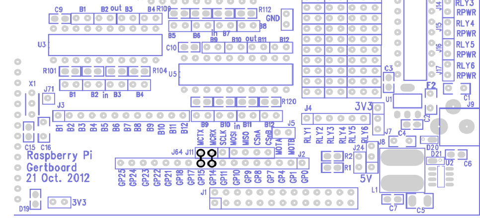
Figure 6: Connections needed to enable serial communication (copied from Gertboard Manual)
Now that all connections are done, and ensuring that the servos are both powered you can upload the code using File → Upload Using Programmer. Having the serial port open in a terminal with minicom as described above, you can now give commands to either of the two servos. Note that initially the two servos are in the neutral position (90 degrees) as initialized in Setup(). For example, by typing l60 you are commanding the motor attached to pin 9 to move at the 60degrees position. By typing r120 the motor attached to pin 10 should move to the 120degrees position.
Controlling the Servo using light
Light dependent resistors (photoresistors) can be used to control a servo. Photoresistors lower their resistance with increasing light striking upon them. In the simplest configuration, the way they can be used to control a servo is explained below:
First, a voltage divider is created using a photoresistor and a normal resistor. In the configuration that we will use (Figure 7), the voltage at the output (Vout) will increase with light exposure. This happens because the voltage across the photoresistor decreases (due to resistance decreasing) and this means more voltage will drop across resistor R.
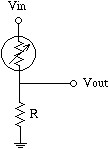
(Figure 7, reference: http://www.societyofrobots.com/schematics_photoresistor.shtml)
An analog input from the Gertboard is connected to Vout such that the change in Vout will be read as a signal between 0 (meaning 0Volts) and 1023 (+3.3V for the Gertboard), according to how much light strikes across the photoresistor. This signal level will then be mapped into a value for the angle of movement of the servo (between 0 and 180 degrees) and that value is written to the servo by using a digital pin, as we did earlier.
Build the small circuit from here: http://www.instructables.com/id/Control-Servo-with-Light/ on a breadboard (replacing Digital Pin D12 with PB4 on J25 and Analog Pin A0 with PC0 on J25). Use a 10k resistor as stated on the diagram. J25 is located on the left hand side of the Gertboard. GND can be taken from J25 connector, from the pin on the right side of PC0. Also, note that the 3V3 pin from the Gertboard (Arduino 5V equivalent) top left side needs to be connected only to the photoresistor, not the servo. Now that all the connections have been done, upload the following code onto the Atmega:
#include <Servo.h>
//Build a new object of type Servo
Servo myservo;
int val;
void setup()
{
//Attach the servo to pin 12 (PB4)
myservo.attach(12);
}
void loop()
{
//Read the value of the analog pin (value between 0 and 1023)
val = analogRead(0);
//Map the signal value to an angle of movement for the servo
ang = map(val, 0, 1023, 0, 179);
//Move the servo at the angle according to the amount of light
myservo.write(ang);
//This sets the speed of movement of the servo
delay(15);
}
See how the servo moves according to the amount of light across it, by restricting the light with your hand or by using a flash-light/lamp.
Making the servo follow a flashlight
Using two photoresistors can make the servo follow the flashlight, as per the video: http://www.youtube.com/watch?v=iEhX27ahreI. The small circuit has been built on a small piece of stripboard, as shown in Figure 8 below. This can be attached onto the servo such that the servo follows the flashlight quite precisely. The connections that need to be done are: pins PC1 and PC0 on the Gertboard (analog pins 1 and 0) connected to the headers as per Figure 8, digital pin PB1 on the Gertboard (pin 9) to the control signal of the servo and all the power and GND connections. Note that in Figure 8 there are three GND connections because it is easier to connect all grounds onto the same place on the stripboard. If the connections are not clear, see the diagram at http://stigern.net/blog/?p=103 for a more detailed diagram, where you need to replace the connections on the Arduino with the ones on the Gertboard.
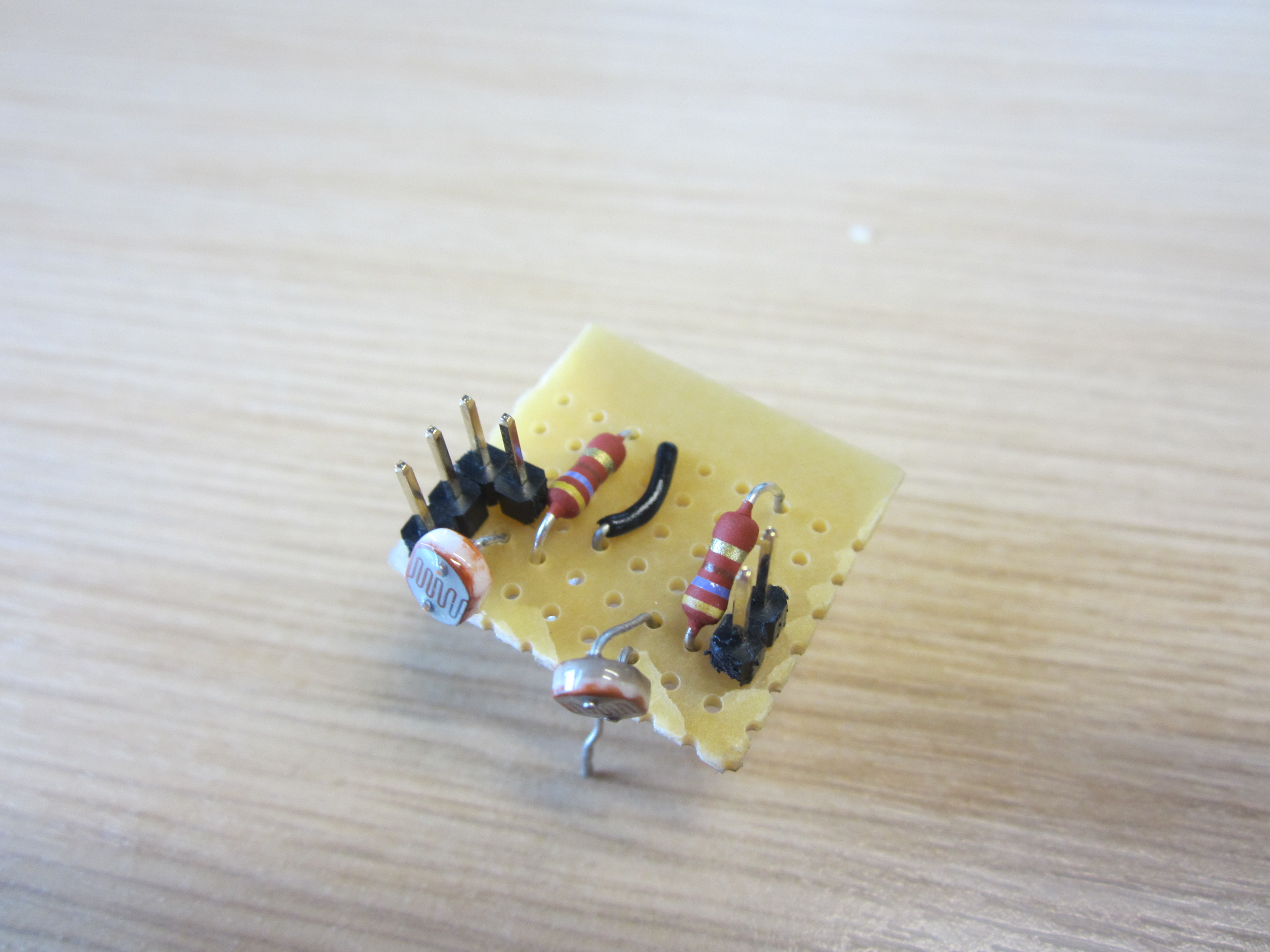
Figure 8: Stripboard with the flashlight tracker circuit
Then you need to upload the following code on the Atmega and you should have a working lighttracker.
#include <Servo.h>
Servo myservo;
int pos = 0; // Variable to store the servo position.
int inputPhotoLeft = 1; // Easier to read, instead of just 1 or 0.
int inputPhotoRight = 0;
int Left = 0; // Store readings from the photoresistors.
int Right = 0; // Store readings from the photoresistors.
void setup()
{
myservo.attach(9); // Attach servo to pin 9.
}
void loop()
{
// Reads the values from the photoresistors to the Left and Right variables.
Left = analogRead(inputPhotoLeft);
Right = analogRead(inputPhotoRight);
// Checks if right is greater than left, if so move to right.
if (Left > (Right +20))
// +20 is the deadzone, so it wont jiggle back and forth.
{
if (pos < 179)
pos=pos+1;
myservo.write(pos);
}
// Checks if left is greater than right, if so move to left.
if (Right > (Left +20))
// +20 is the deadzone, so it wont jiggle back and forth.
{
if (pos > 1)
pos = pos-1;
myservo.write(pos);
}
// Added some delay, increase or decrease if you want less or more speed.
delay(10);
}
http://stigern.net/blog/?p=103