Print this Page

Adafruit RGB/BLue&White LCD Display

1) Overview


This Adafruit plate makes it easy to use a 16×2 Character LCD. Unfortunately, these LCDs do require quite a few digital pins, 6 to control the LCD and then perhaps another 3 to control the RGB backlight for a total of 9 pins. That’s nearly all the GPIO available on a Raspberry Pi! You will either have a RGB LCD Plate or a Blue & White one. The functionality for the two is similar, the only difference is in the colours displayed. You can recognise easily that you have a RGB or Blue&White one by looking at the number of soldered pins above the screen. The RGB one has 18, while the Blue&White one has 16.

This plate is perfect for when you want to build a stand-alone project with its own user interface. The 4 directional buttons plus select button allows basic control without having to attach a bulky computer.

2) Usage

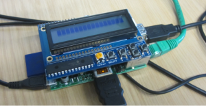
Plug the LCD Plate onto the Pi, using the 26-pin GPIO header such that the LCD Plate will rest above the Raspberry Pi, as shown in below:

LCDPlate


The backlights will not turn on until you have the code running so don’t be alarmed if nothing lights up when you plug in the plate! If you have a ‘positive’ style LCD, you may see some squares on the first line, that’s normal.

Setting up your Pi for I2C

For a more basic introduction to setting up I2C on your Pi then you may wish to take a diversion to this Adafruit tutorial:  http://learn.adafruit.com/adafruits-raspberry-pi-lesson-4-gpio-setup/configuring-i2c

Type in the command sudo nano /etc/modules in order to edit “modules” file and add the following lines:


i2c-bcm2708

i2c-dev

to the end of the file. Then save the file and reboot the Pi (type sudo reboot in the terminal) to enable the hardware I2C driver.

Before you can get started with I2C on the Pi, you’ll need to run through a couple quick steps from the console. Just enter the following commands to add SMBus support (which includes I2C) to Python:


  1. sudo apt-get install python-smbus
  2. sudo apt-get install i2c-tools
i2c-tools isn’t strictly required, but it’s a useful package since you can use it to scan for any I2C or SMBus devices connected to your board.  If you know something is connected, but you don’t know it’s 7-bit I2C address, this library has a great little tool to help you find it:
  1. sudo i2cdetect -y 0 (if you are using a version 1 Raspberry Pi)
  2. sudo i2cdetect -y 1 (if you are using a version 2 Raspberry Pi)
This will search /dev/i2c-0 or /dev/i2c-1 for all address, and if an Adafruit LCD Plate is connected, it should show up at 0x20, as per the figure above. Once both of these packages have been installed, you have everything you need to get started accessing I2C and SMBus devices in Python.

Using the example Python code

The easiest way to get the code onto your Pi is to hook up an Ethernet cable, and clone it directly using ‘git‘. Simply run the following commands from an appropriate location (ex. “/home/pi”):

  1. sudo apt-get install git
  2. git clone https://github.com/adafruit/Adafruit-Raspberry-Pi-Python-Code.git
  3. cd Adafruit-Raspberry-Pi-Python-Code
  4. cd Adafruit_CharLCDPlate
You will also need to install RPi.GPIO, the python library for Pi that allows easy GPIO access. On Raspbian, just run:
sudo apt-get install python-dev
sudo apt-get install python-rpi.gpio

Testing the Library

Once the code has been downloaded to an appropriate folder, and you have your LCD Plate properly connected, you can start with the basic demo display, which is run by simply executing the library file:

  1. sudo python Adafruit_CharLCDPlate.py
If you have a rev 2 (512MB) Pi, or if you’re not getting anything displaying, it might be due to the I2C bus number change in the Pi hardware. Edit Adafruit_CharLCD.py using a command like “nano Adafruit_CharLCD.py” and change the line:
lcd = Adafruit_CharLCDPlate(busnum = 0)
to
lcd = Adafruit_CharLCDPlate(busnum = 1)

Adjusting Contrast

The plate uses a character LCD with an external yellow contrast potentiometer. The first time you use it, adjust the potentiometer in the bottom right (with a screwdriver or something similar) until you see the text clearly. If you don’t upload code to the Pi, some boxes may appear instead, or you may see nothing at all.

Using the library code

Interfacing with the python example code is fairly easy! Inside the Adafruit_CharLCDPlate folder you’ll find a testLCD.py python script. The script does a few things, at the top it imports all the sub-modules. You’ll need to have the Adafruit_I2C.py, Adafruit_MCP230xx.py and Adafruit_CharLCDPlate.py python files to be in the same directory so be sure to copy them to your final destination.

Next it initializes the plate with lcd = Adafruit_CharLCDPlate() – this creates the lcd object and starts communicating with the plate to set up the LCD and buttons. After initialization, you can clear the display with lcd.clear() and write text with lcd.message(“text goes here”) don’t forget that its only 16 characters per line, and it does not automatically wrap lines. To insert a newline use the special ‘\n’ character such as shown in the command: lcd.message(“Adafruit RGB LCD\nPlate w/Keypad!”). Next you can set the backlight with lcd.backlight(lcd.COLORNAME) where COLORNAME is RED, YELLOW, GREEN, TEAL, BLUE, VIOLET for RGB LCD’s or for monochrome LCDs, just use ON and OFF.

Finally, you can ask the plate which buttons are pressed with buttonPressed(lcd.BUTTONNAME) where BUTTONNAME is LEFT RIGHT UP DOWN or SELECT. This is not an interrupt-driven library so you can’t have an interrupt go off when a button in pressed, instead you’ll have to query the button in a loop.

That’s it! If you want to make detailed messages, use the python string formatting commands to create a string and then write that string with message()

http://learn.adafruit.com/adafruit-16×2-character-lcd-plus-keypad-for-raspberry-pi/usage


3) Connectivity test

Here is a python script which can test the internet connectivity on your raspberry pi and display whether there is internet connection, by pinging google. It also displays the Pi`s IP Address on the screen.

The code has been adapted from James Wooley`s “Raspberry PI Pentesting Dropbox Slypi” described here: http://www.youtube.com/watch?v=XkT__rRgLc8 and which can be found here “https://github.com/Xtrato/Slypi

To test your internet connection, simply copy and paste the following code into a new python script and save the script in the folder “Adafruit_CharLCDPlate” from the previous chapter. You can do this by the following steps:

a) Navigate to the directory Adafruit-Raspberry-Pi-Python-Code/Adafruit_CharLCDPlate. If you are in /home,  type:

  1. cd Adafruit-Raspberry-Pi-Python-Code
  2. cd Adafruit_CharLCDPlate

If you did the previous example, you should already be located in this directory

b) Open a new python script by typing nano ConnectivityTest.py (instead of “ConnectivityTest” you can give it any name). A blank file will open in the terminal. Copy and paste the code into this blank file and then save it and close using the Ctrl+x command.

c) Type sudo python ConnectivityTest.py in the terminal. The LCD should show “Connectivity Test” written on the screen. Press “Select” and, if there is connectivity test, a green display should pop-up saying “Testing Connectivity” followed by a yellow screen which will display the IP address of the PI as well as the IP address of ? ?

d) Press Ctrl+c to return to the command line


#!/usr/bin/python
from socket import socket, SOCK_DGRAM, AF_INET
import string
import os
import sys
from time import sleep
from Adafruit_CharLCDPlate import Adafruit_CharLCDPlate
import subprocess
import urllib #Used to display the Public IP address.
from subprocess import PIPE
# Initialize the LCD plate.  Should auto-detect correct I2C bus.  If not,
# pass ‘0’ for early 256 MB Model B boards or ‘1’ for all later versions
lcd = Adafruit_CharLCDPlate(busnum = 1)
def connectivityTest():
    print ‘Connectivity Test’
    #Pings google.com
    thePing = subprocess.Popen(‘ping -c 5 google.com’, shell=True, stdout=PIPE, stderr=PIPE)
    lcd.clear()
    lcd.backlight(lcd.GREEN)
    lcd.message(“Testing\nConnectivity”)
    pingOut, pingErr = thePing.communicate()
    #If the ping fails ping 8.8.8.8
    lcd.clear()
    if len(pingErr) > 0:
        lcd.backlight(lcd.RED)
        thePing = subprocess.Popen(‘ping -c 5 8.8.8.8’, shell=True, stdout=PIPE, stderr=PIPE)
        pingOut, pingErr = thePing.communicate()
        print 1
        #If pinging 8.8.8.8 fails display there is no internet connection
if len(pingErr) > 0:
            lcd.message(“No Internet\nConnection”)
            print 2
        #If pinging 8.8.8.8 succeeds, display there is no DHCP service available for the SlyPi to use.
        else:
            lcd.message(“No DHCP\n Available”)
            print 3
    else:
        privateIP = getPrivateIP()
        publicIP = getPublicIP()
        lcd.backlight(lcd.YELLOW)
        print privateIP
        print publicIP
        #Displays the public and private IP addresses on the LED screen.
        lcd.message(privateIP + ‘\n’ + publicIP)
        sleep(3)
funtionBreak()
def funtionBreak():
    while lcd.buttonPressed(lcd.LEFT):
        os.execl(‘slypi.py’, ”)
def errorCheck(error, failedMessage, succeedMessage):
    lcd.clear()
    if ‘brctl: not found’ in error:
        lcd.backlight(lcd.RED)
        lcd.message(“Failed\nInstall brctl”)
    elif len(error[1]) == 0:
        lcd.backlight(lcd.GREEN)
        lcd.message(succeedMessage)
        sleep(3)
    elif len(error[1]) > 0:
        lcd.backlight(lcd.RED)
        lcd.message(failedMessage)
        sleep(2)
        os.execl(‘slypi.py’, ”)
    error = 0
def getPublicIP():
    publicIPUrl = urllib.urlopen(“http://my-ip.heroku.com/”)
    return publicIPUrl.read()
def getPrivateIP():
    s = socket(AF_INET, SOCK_DGRAM)
    s.connect((‘google.com’, 0))
    privateIp = s.getsockname()
    return privateIp[0]
#Contains all modules which can be run on the device. The key is the displayed name on the LCD and the value is the function name
modules = {‘Connectivity\nTest’: ‘connectivityTest’}
displayText = modules.keys()
# Clears the display
lcd.clear()
# Checks if the script has been run as root.
if os.getuid() == 0:
    menuOption = 0
    #lcd.backlight(lcd.BLUE)
    lcd.message(“SlyPi\nPress Select”)
else:
    lcd.backlight(lcd.BLUE)
    lcd.message(“Be sure to\nRun as root”)
#The following while loop controls the LCD menu and the control using the keypad through the menu.
while True:
    if lcd.buttonPressed(lcd.SELECT):
        sleep(0.5)
        lcd.clear()
        lcd.message(displayText[menuOption])
        while True:
            lcd.backlight(lcd.BLUE)
            if lcd.buttonPressed(lcd.DOWN):
                menuOption = menuOption + 1
                if menuOption > len(modules) – 1:
                    menuOption = 0
                lcd.clear()
                lcd.message(displayText[menuOption])
                sleep(0.5)
            if lcd.buttonPressed(lcd.UP):
                menuOption = menuOption – 1
                if menuOption < 0:
                    menuOption = len(modules) – 1
                lcd.clear()
                lcd.message(displayText[menuOption])
                sleep(0.5)
            if lcd.buttonPressed(lcd.SELECT):
                globals().get(modules[displayText[menuOption]])()
                sleep(0.5)
                break
            if lcd.buttonPressed(lcd.LEFT):
                print “left”
                menuOption = 0
                break

Permanent link to this article: https://blog.soton.ac.uk/pi/modules-available/adafruit-rgb-lcd-display/