Architectural Design

For our project we proposed 3 tier MVC architecture. The reason for proposing MVC is that gives data the ability to change independently and allows presentation of the same data in different ways (Pressman, 2010). With 3-layered architecture gives more secure accessing to data and authentication can be enabled in each layer (Sommerville, 2010). We believe that merging MVC with 3 Layered architecture gives more secure and enhance reuse functionality.

Architucture

References:

Sommerville, I. (2010) Software Engineering >INTERNATIONAL EDITION <. 9th edn. Harlow: Pearson Education (US)

Pressman (2000) Software Engineering: A Practitioner’s Approach (McGraw-Hill International Editions: Compute… 5th edn. United States: McGraw Hill Higher Education

Project Process

This portfolio is a result of following certain process methodologies. As with more traditional approach, the team roles were clearly defined and most of the tasks were allocated at the start of the project. A project plan with milestones was also prepared.

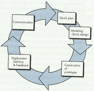
The processes of developing the portfolio and designing our social network have had several elements of prototyping, one of the popular prescriptive (traditional) methods:

  • Going through multiple iterations in order to provide finished work
  • Discovering new stakeholder’s requirements with each iteration
  • Response to feedback from our mentor, who acted effectively as our Client
Scan_20150430

The Prototyping Paradigm (Pressman, R.S., 2010)

However, we have also incorporated some strong agile components to it, such as:

  • Frequent and regular meetings as a group (on weekly basis) plus extra meetings in subgroups (e.g. graphic designers) as appropriate but also informal Facebook conversations
  • Regular meetings with our mentor
  • Spare meeting times used for brainstorming and free circulation of ideas
  • Balancing workload, requirements and product features in order to meet the deadlines
  • Role flexibility: while everyone had their role assigned, team members were able to support each other in areas outside their core responsibilities

References

  1. Pressman, R.S., 2010. Software Engineering: A Practitioner’s Approach 7th ed., London: McGraw-Hill.

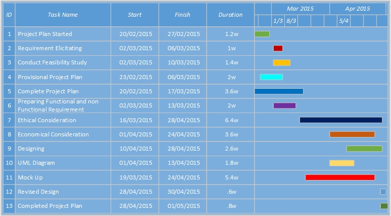
Project Schedule-Gantt Chart

We made use of Gantt Chart to manage the requirements of the project. Besides we met weekly to assure the progress of the plan. Also, between the weekly meetings we used facebook group to communicate and support each other. Lastly, Google Drive was used for the tasks that was developed by more than one memeber of the team so that they can work on it in parallel. The reason of using the mentioned tools and techniques was the familiarity of the team with them. So that to work on the tasks immediately without wasting time to learn new tools to communicate.

Gantt Chart 2

System Modeling

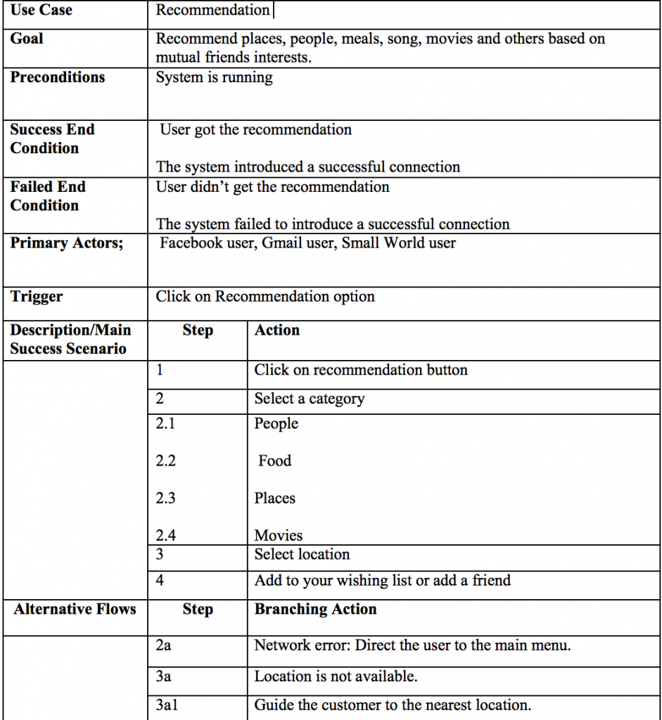
The system requirements that have been collected from team members (since the permission for an ethical approvement got delayed) and feasibility study have been modelled using textual use cases for the most outstanding functions and that make the core of the small.world application. This gives a better understanding of what the system is expected to do and how the user is expected to use it.


Recommendation use case

is an example of the developed use cases. for a detailed view, read use cases.

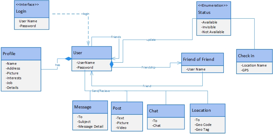
Class Diagram

The Class is the static structure of the system. The diagram illustrates the system classes, attributes, operations and interrelationship between them (Ambler, 2014). The class diagram is divided into two main sections, class name with blue background, attributes beginning with a minus sign (-) indicate a private attribute.The arrows show the associations between classes with labels indicating the nature of the relations. For example, User class is associated with Profile class, it means each user has it is own profile.For simplicity, only the main operations are included in these classes. As in requirements mentioned, the User class has Chat, Post, and Message class. To make the class diagram clearer and easily understood, some operations have been eliminated from the figure.


SmallWorld_Class Diagram1

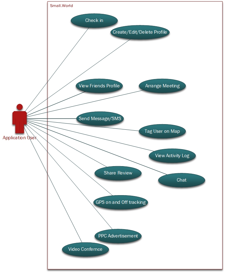
Use Case Diagram for Small.World

This is the use case diagram for Small.World.

The Use case diagram below represents the main possible interactions of actors/stakeholders of Small.World. This is inline with the functional requiremnt of the application. The user first need to create account through multiple options such as google+, facebook or create account in Small.World. When the user login they can do different types of activity as shown in the diagram.
The Application, has many options that allows user to do videio conferencing, tag user on map and store past activity log, GPS tracking and pay per click advertisements are some of them.

*Visio Professional by microsoft is used to draw use case diagram because it has significant generralised drawing tools that allows you to produce any diagram very quickly. Asmallworld - Copy